Smoking & cooking zone
Curing colour development, drying, hot smoking, cooking, scalding, hot-air cooking and venting – or a dedicated cooking zone designed for the project.

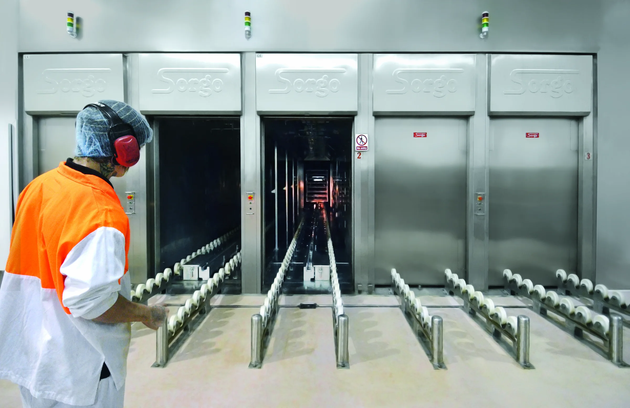
AUTOMATED INDUSTRIAL LINES
SORGO continuous systems combine smoking, cooking, showering and blast chilling in a modular industrial line. Single- or double-row configurations transport trolleys, racks or hanging products synchronously through the process zones and deliver the finished product at a defined core temperature.
APPLICATION AREAS
PROCESS SEQUENCE
CONTINUOUS SYSTEM ENGINEERING
SORGO continuous systems combine heat treatment and blast chilling in a single structural unit. While one batch is brought to core temperature in the cooling zone, the next is already running in the smoking or cooking zone – for high output without unnecessary transfer and waiting times.
Curing colour development, drying, hot smoking, cooking, scalding, hot-air cooking and venting – or a dedicated cooking zone designed for the project.
Fully insulated lifting or hinged doors separate process areas, open in time with the conveying sequence and limit energy losses.
Recirculating-air cooling, cooling shower, optional mist shower and drying down to the defined core temperature.
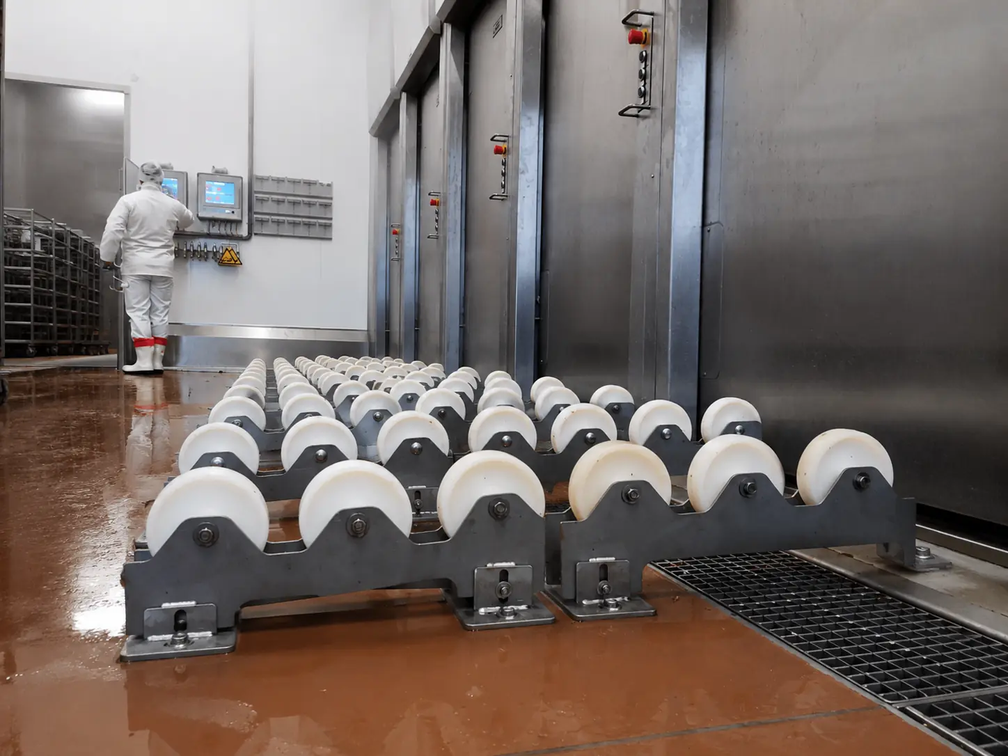
LOADING & TRANSPORT
The level of automation ranges from manual loading to fully automatic receiving, transfer and discharge. The design follows actual factory logistics and can hygienically connect production and packaging areas.
Monitored rack-and-pinion drives with push rods and carriers precisely position and move trolleys through the line.
Configurations with ceiling-guided overhead rails and product-specific racks are possible for hanging products.
Infeed and outfeed roller conveyors and automatic transfer stations connect the line to upstream and downstream areas.
PROJECT MODULES
Product, hourly output, trolley format, building, utilities and hygiene concept determine the combination. The following configurations are standard, alternatives or options depending on the project.
Each trolley position receives its own recirculation fan with central suction. Two-speed or continuously variable air recirculation and specially shaped nozzles distribute conditioned air across the entire load.
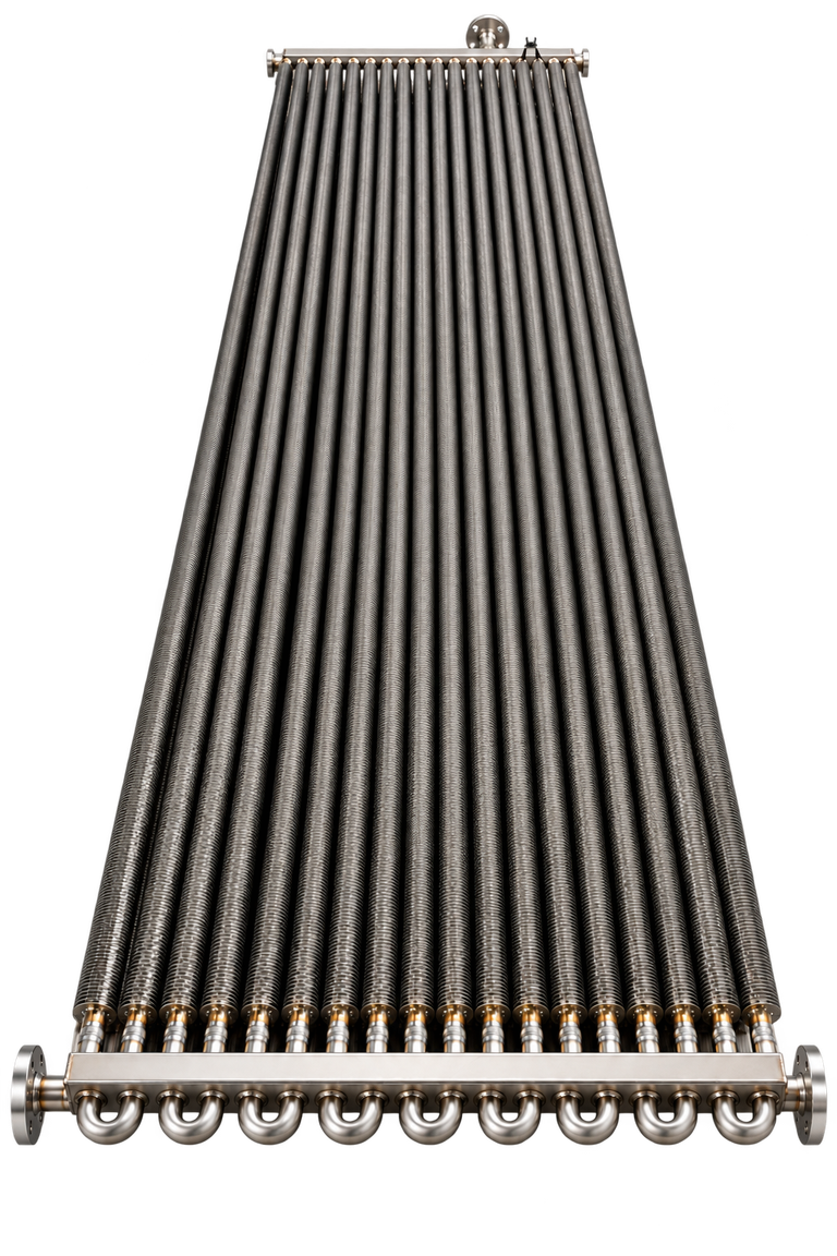
Heating with electricity, gas, oil or high-pressure steam.
With steam, cooking uses low-pressure saturated steam at 0.5 bar.
The cooling zone is equipped with an integrated cooling shower. Optionally, a stainless steel two-fluid nozzle per trolley uses water and compressed air to remove additional heat through microfine mist with low water consumption.
Fully insulated pneumatic lifting doors are pressed against the door frame in sync with the transport sequence. Depending on layout, swing doors, hinged doors, fail-safe functionality and interlocking between low-risk and high-risk areas are possible.
Friction, smouldering or wood-chip smoke is integrated fully automatically. Smoke intensity, dampers and the variable-frequency-controlled exhaust fan can be precisely controlled for each process; smoke paths can be included in cleaning.
Programme-controlled cleaning with dosing, pressure boosting and fresh-water rinsing can clean process zones separately. SORGO X1 operates the line at the inlet and outlet; SORGO Inspect centrally documents programmes, batches, curves, messages and alarms in the browser.
Modular stainless steel sections with smoke- and vapour-tight welds, full insulation and temperature- and acid-resistant seals form the basis. Depending on the process zone, 1.4301 or 1.4571 is used. Smooth, heavily reinforced floors, trolley guides and monitored drains support load-bearing capacity, hygiene and operational safety.
HEATING
SORGO ENGINEERING
While one batch cools, the next is already running in the heating zone. This increases output and avoids unnecessary downtime.
Load before the end of the shift, process automatically and remove the chilled finished product the next day.
Synchronised doors and automatic transfers connect production and packaging areas with clearly separated process zones.
Rapid, controlled cooling reduces weight loss and can eliminate intermediate storage and additional cold-room requirements.
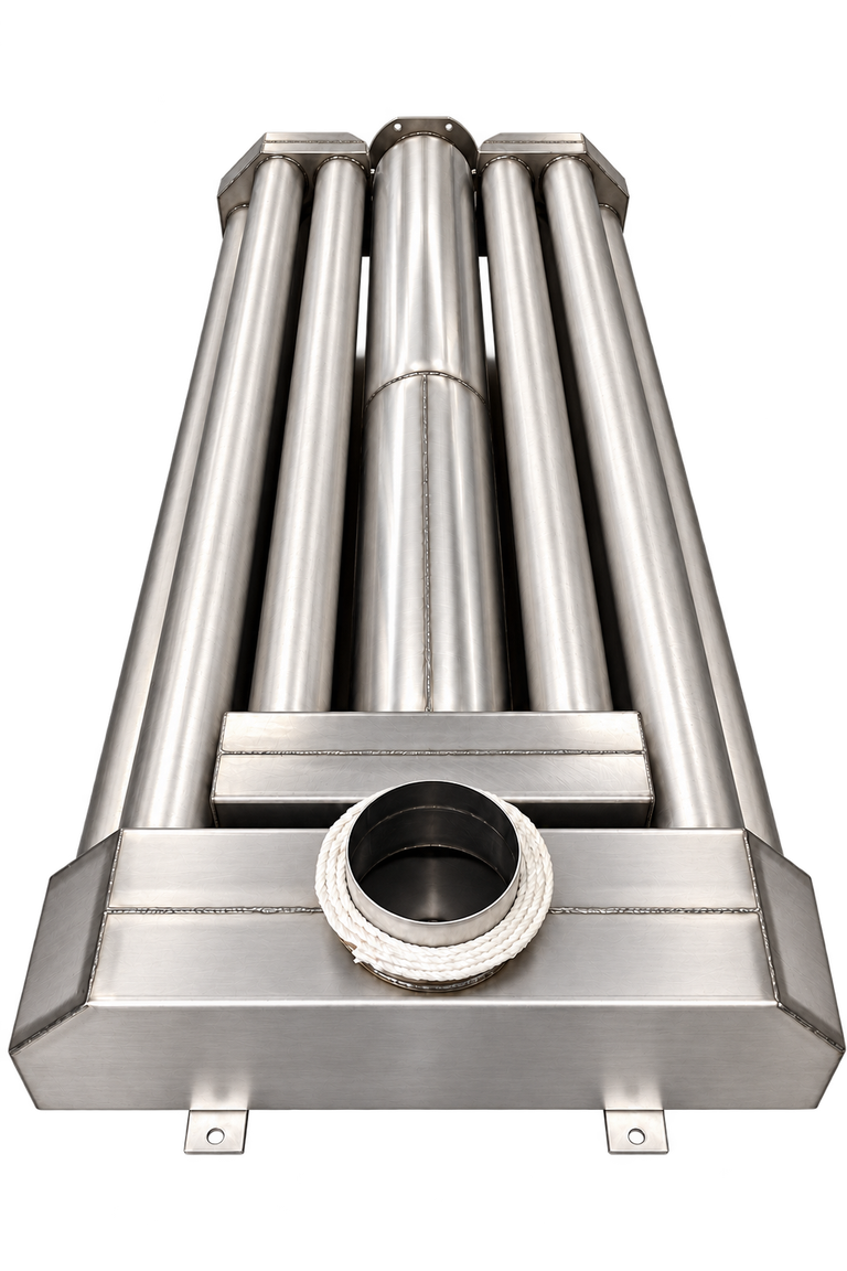
Smoke generators
Smoke generator, smoke path and safety are planned as one system.
Smoke generatorsCONTROL & PROCESS DOCUMENTATION
Intuitive operation on a 15.6-inch industrial touchscreen, storable programmes and precise process control. Also discover SORGO INSPECT for central documentation and optional remote operation via smartphone or tablet.
The control system coordinates the process zones, transport sequences and interfaces actually planned for the line.
Discover control & process documentation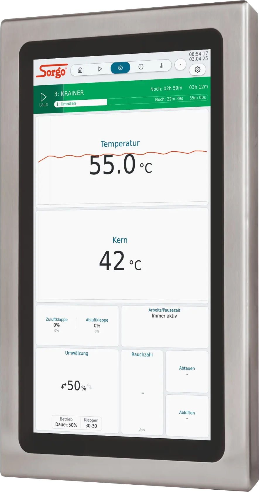
CONFIGURATION & DETAILS
TECHNICAL DESIGN
Select the trolley count for the continuous line. Section 1 and section 2 are automatically designed with equal capacity; capacities, connections and dimensions update together.
One selection controls both process sections connected by the transfer airlock.
 Curing colour development & pre-dryingSmoking
 Cooking & thermal processing
 Showering
 Chilling & crust freezing
Continuous 2+2
Curing colour development & pre-dryingSmokingCooking & thermal processing| Type | Trolleys | Trolley dimensions | System dimensions | Heat supply | Cooking / humidification | Electrical connected load |
|---|---|---|---|---|---|---|
| HR 6.000Smoking/cooking section | 2Section 1 | 1,000 × 1,000 × 2,000 mm | B 1450 x D 2350 x H 2820 mmSystem housing+ 300 mm air recirculation motor | 60 kWHeating capacity · Electric | Cold or hot water supplyElectric | 72,5 kWFriction smoke · Standard versionSmoke generator electrical load: 5,5 kW |
Continuous 2+2
ShoweringChilling & crust freezing| Type | Trolleys | Trolley dimensions | System dimensions | Heating capacity / cooking | Cooling capacity | Electrical connected load |
|---|---|---|---|---|---|---|
| IK 6.000Blast chilling section | 2Section 2 | 1,000 × 1,000 × 2,000 mm | B 1450 x D 2350 x H 2820 mmSystem housing+ 300 mm air recirculation motor | Without cooking functionNot selected | 30 kWRefrigerant · Glycol15 kW per trolley at −15 °C flow temperature | 7 kW |
Total values are based on two equally sized sections.
Overall dimensions use the common width and height of both sections; depth is the sum of sections 1 and 2. The transfer airlock, door system, transport and local installation conditions are defined in the project. All performance and dimensional data are indicative.
The complete table with your current selection as an A3 landscape PDF.
BROCHURE
A compact PDF covering the product overview, processes and equipment options.
TAILORED TO YOUR NEEDS
Capacity, product, trolley format, energy supply, room layout and level of automation determine the solution. SORGO plans every system for the actual operating workflow – including controls, smoke system, cleaning, documentation, installation and commissioning.