
HIGH TEMPERATURE · CROSS-FLOW
Roasting, cooking and baking – uniform results on every product level.
SORGO roasting/baking systems combine high process temperatures with reversing horizontal cross-flow. For meatloaf, crusted ham and other products, they deliver uniform colour, cooking and crust formation over the entire trolley height.
APPLICATION AREAS
Roasting/baking systems
Leberkäse meatloafCrusted hamRoasted & baked productsHot-air cooked products
PROCESS SEQUENCE
01Curing colour development
02Drying
03Cooking
04Roasting
05Hot-air cooking
06Baking
07Venting
ROASTING · BAKING · HOT-AIR COOKING
Roasting/baking systems for high temperatures and uniform product colour.
The SORGO roasting/baking/cooking system combines a highly insulated stainless steel chamber with reversing horizontal cross-flow. It is suitable for meatloaf, crusted ham and products requiring uniform roasting, cooking or baking over the entire trolley height.
REVERSING CROSS-FLOW
Discharge from the left, flow horizontally through the product, extract on the right – then reverse automatically.
Reversing cross-flow is adapted to the product, trolley loading and system geometry. Pneumatically operated reversing dampers change the airflow direction under programme control. A dedicated recirculation fan per trolley position supports uniform treatment across all product levels.
01
Process air is distributed through a side duct.
02
It flows horizontally through the products across the trolley height.
03
The opposite duct returns the air to the recirculation system.
04
The reversing dampers automatically reverse the airflow direction.
TARGETED AIRFLOW
Tailored to the product and load.
Three air supply configurations are available for different products and loads. The appropriate solution is designed for the trolley and process.
- 01
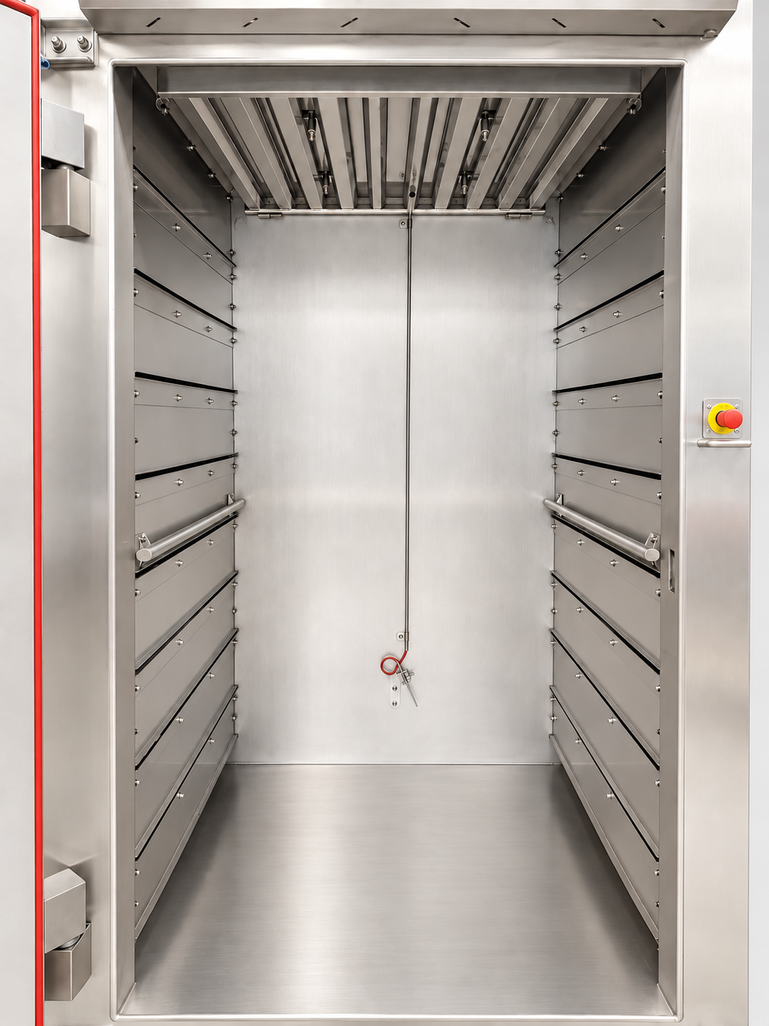
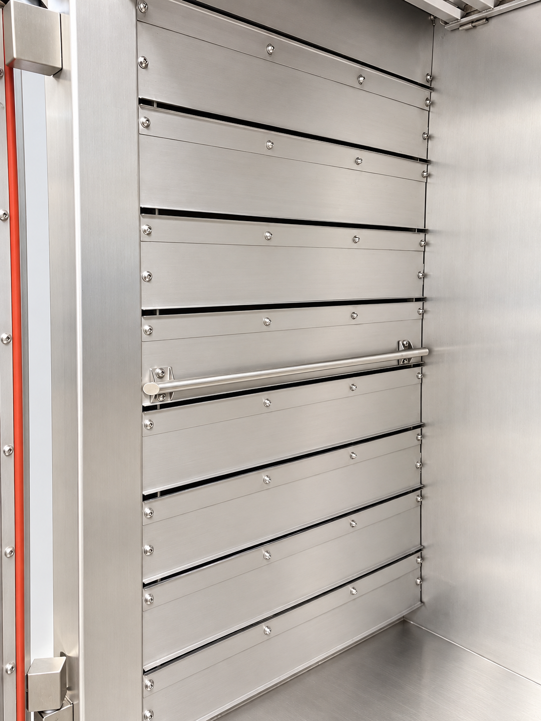
Adjustable air slots
Air supply from left, right and centre. Slot height, number and settings follow the rack levels and trolley loading.
- 02
Perforated-sheet airflow
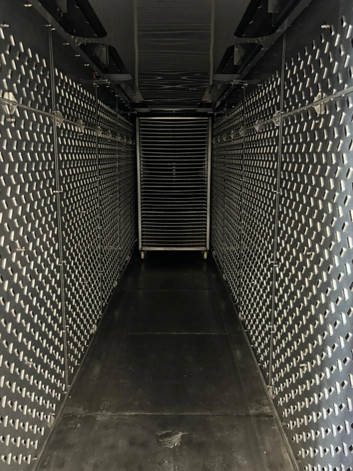
Specially shaped perforations direct conditioned air into the treatment chamber.
- 03
Nozzle airflow
Specially shaped nozzles direct conditioned air precisely into the treatment chamber.
Process benefits
- Uniform product treatment over the trolley height and loading depth
- Continuously variable air recirculation via variable-frequency drive
- Sectionally adjustable air extraction
- No direct radiant heat on upper product levels
- Heavy-duty reinforced floor for up to 2,500 kg per trolley
- 250 mm thick, fully insulated loading door
- Optional pneumatic door opener
LOADING DOOR
250 mmFully insulated constructionDesigned for high process temperatures.
The solid loading door has a continuous silicone seal. It resists grease, acids and high temperatures and supports reliable sealing during cooking and baking.
- 250 mm thick, fully insulated door
- Continuous silicone seal
- Robust closing mechanism for everyday production
Base steam heating at 30 kW per trolley reaches a maximum of 110 °C. Supplementary electric heating is required from 150 °C.
The reference data describe a two-trolley configuration. Trolley count, temperature, heating type, airflow and dimensions are designed for each project; additional heating capacities can be selected in the technical design section.
INSIDE THE DESIGN
Cooking chamber details.
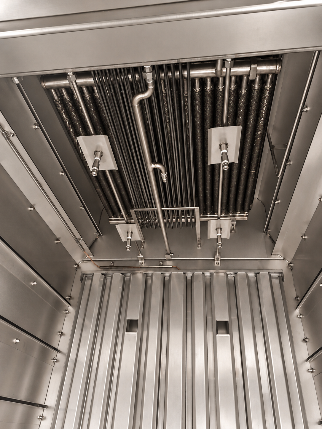
The air slots are adapted to trolley loading and occupied rack levels. The fold-down drip tray provides access to the upper system area.
SORGO ENGINEERING
Technology that creates measurable added value.
Reversing cross-flow
Pneumatically operated reversing dampers automatically change the horizontal airflow direction.
Up to +250 °C
High temperature range for demanding roasting, cooking and baking processes – depending on heating type and selected supplementary capacity.
Active airflow at every trolley
A dedicated recirculation fan per trolley position supports uniform results.
Heavy loads & hygiene
Vapour-tight welded stainless steel modules, solid doors and a reinforced system floor.
OPTIONAL CIP CLEANING
Defined cleaning. Matched to the system.
The CIP cleaning system is available as an option. One cleaning station can clean several connected systems sequentially. External CIP pipes are not insulated.
Cleaning scope, dosing and sequences are adapted to the components actually installed and the operational cleaning procedure.
CONTROL & PROCESS DOCUMENTATION
SORGO SCS X1 – your processes under control.
Intuitive operation on a 15.6-inch industrial touchscreen, storable programmes and precise process control. Also discover SORGO INSPECT for central documentation and optional remote operation via smartphone or tablet.
Available functions depend on the specific roasting/baking configuration; smoke functions are not assumed here.
Discover control & process documentation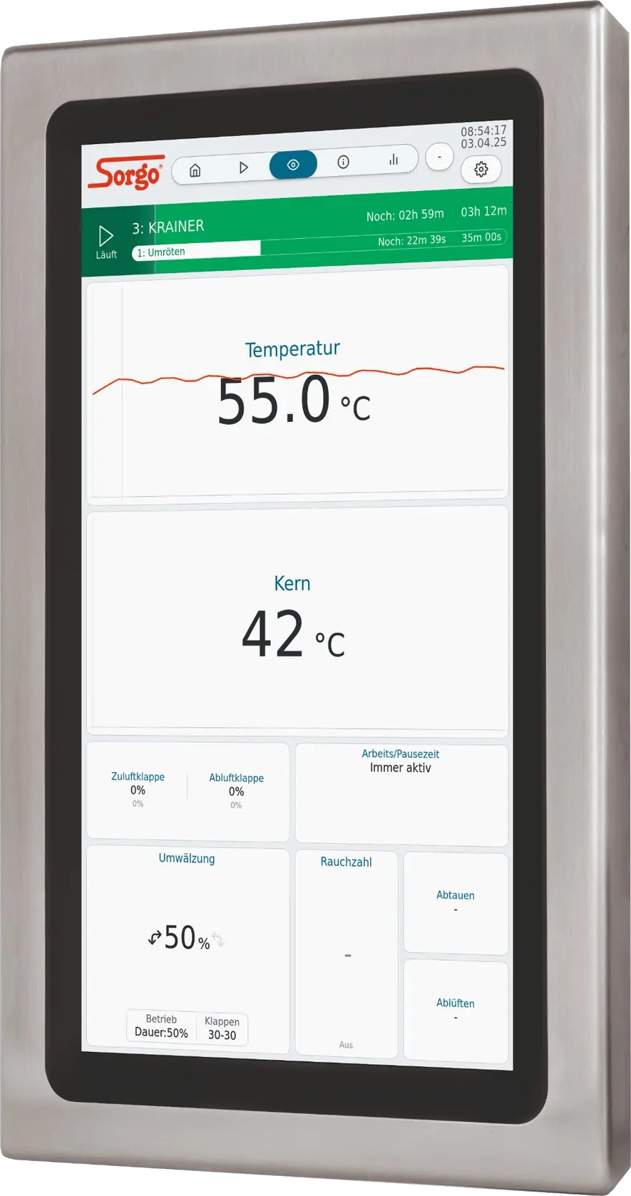
CONFIGURATION & DETAILS
Genuine SORGO technology. Engineered down to the details.
01 / 02
TECHNISCHE AUSLEGUNG
BK-Baugrößen und Heizleistung im Überblick.
Wählen Sie Heizungsart und Prozesstemperatur. Die Kochfunktion gehört zur Standardausstattung.
01
Ausführung konfigurieren
Die BK-Anlagen sind einreihig ausgelegt; die Heizung gehört bei jeder Anlage zur Grundausstattung.
Gewählte AusführungElektro · Bis 150 °C · Kochen fest integriert
Die Elektro-Grundheizung mit 30 kW je Wagen erreicht bis zu 150 °C. Für 180 °C und mehr wird die elektrische Heizleistung erhöht.
Bei Elektro-, Gas- und Ölheizung erfolgt die Befeuchtung über Kalt- oder Warmwassereinspeisung.
02
Heizleistung und Abmessungen
| Typ | Wagen | Wagenmaß | Anlagenabmessungen | Heizung / Temperatur | Kochfunktion | E-Anschlussleistung |
|---|---|---|---|---|---|---|
| BK3000 | 11-reihig | 1000 x 1000 x 2000 mm | B 1450 x T 1290 x H 2820 mmAnlagengehäuse+ 300 mm Umluftmotor | 30 kW Heizleistung gesamtGrundheizung · Elektro · 30 kW je Wagen × 1 = 30 kW · bis 150 °CGewählter Temperaturbereich: Bis 150 °C | Kalt- oder WarmwassereinspeisungKochen fest integriert | 34 kWElektro-Heizleistung 30 kW+ 4 kW Umluft und Nebenverbraucher |
| BK6000 | 21-reihig | 1000 x 1000 x 2000 mm | B 1450 x T 2350 x H 2820 mmAnlagengehäuse+ 300 mm Umluftmotor | 60 kW Heizleistung gesamtGrundheizung · Elektro · 30 kW je Wagen × 2 = 60 kW · bis 150 °CGewählter Temperaturbereich: Bis 150 °C | Kalt- oder WarmwassereinspeisungKochen fest integriert | 67 kWElektro-Heizleistung 60 kW+ 7 kW Umluft und Nebenverbraucher |
| BK9000 | 31-reihig | 1000 x 1000 x 2000 mm | B 1450 x T 3440 x H 2820 mmAnlagengehäuse+ 300 mm Umluftmotor | 90 kW Heizleistung gesamtGrundheizung · Elektro · 30 kW je Wagen × 3 = 90 kW · bis 150 °CGewählter Temperaturbereich: Bis 150 °C | Kalt- oder WarmwassereinspeisungKochen fest integriert | 103 kWElektro-Heizleistung 90 kW+ 13 kW Umluft und Nebenverbraucher |
| BK12000 | 41-reihig | 1000 x 1000 x 2000 mm | B 1450 x T 4520 x H 2820 mmAnlagengehäuse+ 300 mm Umluftmotor | 120 kW Heizleistung gesamtGrundheizung · Elektro · 30 kW je Wagen × 4 = 120 kW · bis 150 °CGewählter Temperaturbereich: Bis 150 °C | Kalt- oder WarmwassereinspeisungKochen fest integriert | 136 kWElektro-Heizleistung 120 kW+ 16 kW Umluft und Nebenverbraucher |
| BK15000 | 51-reihig | 1000 x 1000 x 2000 mm | B 1450 x T 5600 x H 2820 mmAnlagengehäuse+ 300 mm Umluftmotor | 150 kW Heizleistung gesamtGrundheizung · Elektro · 30 kW je Wagen × 5 = 150 kW · bis 150 °CGewählter Temperaturbereich: Bis 150 °C | Kalt- oder WarmwassereinspeisungKochen fest integriert | 169 kWElektro-Heizleistung 150 kW+ 19 kW Umluft und Nebenverbraucher |
| BK18000 | 61-reihig | 1000 x 1000 x 2000 mm | B 1450 x T 6680 x H 2820 mmAnlagengehäuse+ 300 mm Umluftmotor | 180 kW Heizleistung gesamtGrundheizung · Elektro · 30 kW je Wagen × 6 = 180 kW · bis 150 °CGewählter Temperaturbereich: Bis 150 °C | Kalt- oder WarmwassereinspeisungKochen fest integriert | 202 kWElektro-Heizleistung 180 kW+ 22 kW Umluft und Nebenverbraucher |
| BK24000 | 81-reihig | 1000 x 1000 x 2000 mm | B 1450 x T 8840 x H 2820 mmAnlagengehäuse+ 300 mm Umluftmotor | 240 kW Heizleistung gesamtGrundheizung · Elektro · 30 kW je Wagen × 8 = 240 kW · bis 150 °CGewählter Temperaturbereich: Bis 150 °C | Kalt- oder WarmwassereinspeisungKochen fest integriert | 268 kWElektro-Heizleistung 240 kW+ 28 kW Umluft und Nebenverbraucher |
| BK30000 | 101-reihig | 1000 x 1000 x 2000 mm | B 1450 x T 11000 x H 2820 mmAnlagengehäuse+ 300 mm Umluftmotor | 300 kW Heizleistung gesamtGrundheizung · Elektro · 30 kW je Wagen × 10 = 300 kW · bis 150 °CGewählter Temperaturbereich: Bis 150 °C | Kalt- oder WarmwassereinspeisungKochen fest integriert | 334 kWElektro-Heizleistung 300 kW+ 34 kW Umluft und Nebenverbraucher |
| BK36000 | 121-reihig | 1000 x 1000 x 2000 mm | B 1450 x T 13160 x H 2820 mmAnlagengehäuse+ 300 mm Umluftmotor | 360 kW Heizleistung gesamtGrundheizung · Elektro · 30 kW je Wagen × 12 = 360 kW · bis 150 °CGewählter Temperaturbereich: Bis 150 °C | Kalt- oder WarmwassereinspeisungKochen fest integriert | 400 kWElektro-Heizleistung 360 kW+ 40 kW Umluft und Nebenverbraucher |
Planungshinweis
BK3000 und größere Baugrößen übernehmen Wagenmaße und Gehäuse-Richtmaße aus der vorhandenen Auslegung. Zusätzlich zum Anlagengehäuse sind 300 mm für den Umluftmotor vorgesehen. Die Temperatur- und Leistungswerte sind Planungsrichtwerte; Wärmebedarf, Aufheizzeit und Medienanschlüsse werden für Produkt, Beschickung und Einbausituation projektspezifisch bestätigt.
Die vollständige Tabelle mit Ihrer aktuellen Auswahl als PDF im A3-Querformat.
TAILORED TO YOUR NEEDS
Your system is developed around your process.
Capacity, product, trolley format, energy supply, room layout and level of automation determine the solution. SORGO plans every system for the actual operating workflow – including heat supply, controls, cleaning, documentation, installation and commissioning.