
Stainless steel 1.4571 (V4A) for the system interior and internal floor.
COOKING · THERMAL PROCESSING · CORE TEMPERATURE
Precise cooking processes. Reproducible for every batch.
SORGO cooking systems are designed for each project to suit the product, trolley format, capacity and available heat supply. Cooking also remains a standard process of the SORGO hot-smoking system.
APPLICATION AREAS
Cooking systems
Meat & sausagePoultryPlant-basedConvenience foods
FIXED PROCESS FUNCTION
01Loading
02Pre-cooking
03Cooking & thermal processing
04Control core temperature
05Unloading
KONSTRUKTION & HYGIENE
Built for continuous use in food production.
The construction is hygienic, robust and easy to service, tailored to the planned cooking process.
Stainless steel 1.4301 (V2A) for the system exterior.
The cooking system has heating; cooling and refrigerant selection are not part of the technical design of this product group.
Trolley count, row arrangement, trolley dimensions and door configuration form the basis of the detailed construction.
SORGO AIRFLOW · PRODUCT YIELD
Uniform results with the lowest possible weight loss.
One fan per trolley position
Each trolley position has its own fan motor with a stainless steel impeller manufactured in-house by SORGO.
High air recirculation capacity
Air capacity is designed for short, controlled processes and the highest possible product yield.
Uniform throughout the trolley
Air distribution is designed for comparable results at the top, bottom, centre, left and right of the trolley.
Easy to maintain
Individual fans can be serviced selectively and replaced separately if required.
Continue production
In multi-trolley systems, functioning trolley positions can continue to be used if an individual fan fails.
Reproducible cooking
Process control and core temperature regulation support repeatable results from batch to batch.
CONTROL & PROCESS DOCUMENTATION
SORGO SCS X1 – your processes under control.
Intuitive operation on a 15.6-inch industrial touchscreen, storable programmes and precise process control. Also discover SORGO INSPECT for central documentation and optional remote operation via smartphone or tablet.
The cooking function is an integral part of the system. Cooling functions are not listed as standard equipment; optional showering and cleaning functions appear only when the corresponding equipment is installed.
Discover control & process documentation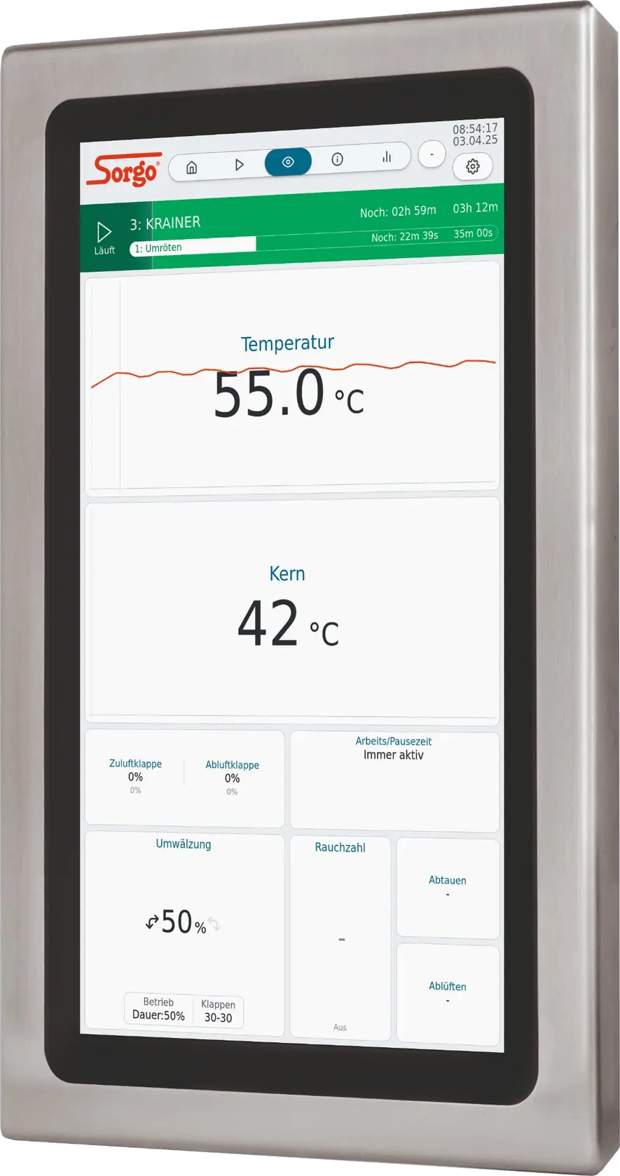
AUSFÜHRUNG & DETAILS
Echte SORGO Technik. Bis ins Detail konstruiert.
Fotos folgen.
TECHNISCHE AUSLEGUNG
Baugrößen und Kochleistung in einer klaren Übersicht.
Die Kochfunktion ist bei jeder KK-Anlage fest integriert. Wählen Sie Heizungsart und Bodenaufstellung; Kühlleistung und Kältemedien sind bewusst nicht Bestandteil dieser Auslegung.
01
Ausführung konfigurieren
Die Kochfunktion ist bei jeder KK-Anlage fest integriert. Wählen Sie Heizungsart und Bodenaufstellung; Kühlleistung und Kältemedien sind bewusst nicht Bestandteil dieser Auslegung.
Gewählte AusführungKochen fest integriert · Elektro · 1-reihig
Bei Elektro-, Gas- und Ölbeheizung erfolgt die Befeuchtung über Kalt- oder Warmwassereinspeisung.
Bei eingebauter Heizung: 30 kW je Wagen.
Kühldusche, Zweistoff-Zerstäuberdüse je Wagenstellplatz und CIP-Reinigung bleiben separat ausgewiesene Optionen; daraus entsteht keine Intensivkühlfunktion.
02
Kochleistung und Abmessungen
| Typ | Wagen | Wagenmaß | Anlagenabmessungen | Heizleistung / Kochen | E-Anschlussleistung |
|---|---|---|---|---|---|
| KK3000 | 11-reihig | 1000 x 1000 x 2000 mm | B 1450 x T 1290 x H 2820 mmAnlagengehäuse+ 300 mm Umluftmotor | 30 kWHeizleistung · ElektroKalt- oder Warmwassereinspeisung | 34 kWHeizleistung: 30 kW |
| KK6000 | 21-reihig | 1000 x 1000 x 2000 mm | B 1450 x T 2350 x H 2820 mmAnlagengehäuse+ 300 mm Umluftmotor | 60 kWHeizleistung · ElektroKalt- oder Warmwassereinspeisung | 67 kWHeizleistung: 60 kW |
| KK9000 | 31-reihig | 1000 x 1000 x 2000 mm | B 1450 x T 3440 x H 2820 mmAnlagengehäuse+ 300 mm Umluftmotor | 90 kWHeizleistung · ElektroKalt- oder Warmwassereinspeisung | 100 kWHeizleistung: 90 kW |
| KK12000 | 41-reihig | 1000 x 1000 x 2000 mm | B 1450 x T 4520 x H 2820 mmAnlagengehäuse+ 300 mm Umluftmotor | 120 kWHeizleistung · ElektroKalt- oder Warmwassereinspeisung | 133 kWHeizleistung: 120 kW |
| KK15000 | 51-reihig | 1000 x 1000 x 2000 mm | B 1450 x T 5600 x H 2820 mmAnlagengehäuse+ 300 mm Umluftmotor | 150 kWHeizleistung · ElektroKalt- oder Warmwassereinspeisung | 166 kWHeizleistung: 150 kW |
| KK18000 | 61-reihig | 1000 x 1000 x 2000 mm | B 1450 x T 6680 x H 2820 mmAnlagengehäuse+ 300 mm Umluftmotor | 180 kWHeizleistung · ElektroKalt- oder Warmwassereinspeisung | 199 kWHeizleistung: 180 kW |
| KK24000 | 81-reihig | 1000 x 1000 x 2000 mm | B 1450 x T 8840 x H 2820 mmAnlagengehäuse+ 300 mm Umluftmotor | 240 kWHeizleistung · ElektroKalt- oder Warmwassereinspeisung | 265 kWHeizleistung: 240 kW |
| KK30000 | 101-reihig | 1000 x 1000 x 2000 mm | B 1450 x T 11000 x H 2820 mmAnlagengehäuse+ 300 mm Umluftmotor | 300 kWHeizleistung · ElektroKalt- oder Warmwassereinspeisung | 331 kWHeizleistung: 300 kW |
| KK36000 | 121-reihig | 1000 x 1000 x 2000 mm | B 1450 x T 13160 x H 2820 mmAnlagengehäuse+ 300 mm Umluftmotor | 360 kWHeizleistung · ElektroKalt- oder Warmwassereinspeisung | 397 kWHeizleistung: 360 kW |
Planungshinweis
Die Höhe wird getrennt für das Anlagengehäuse und die zusätzlichen 300 mm für den Umluftmotor angegeben. Alle Werte sind Richtwerte; jede SORGO Kochanlage wird individuell ausgelegt und gefertigt.
Die vollständige Tabelle mit Ihrer aktuellen Auswahl als PDF im A3-Querformat.
BROCHURE
Technical information to take away.
A compact PDF covering the product overview, processes and equipment options.
TAILORED TO YOUR NEEDS
Your cooking system is developed around your process.
Product, capacity, trolley format, energy supply, room layout and level of automation determine the final solution.