Recirculating-air cooling and cooling shower
Cooling takes place in parallel through powerful, targeted recirculating air and an integrated cooling shower. This removes heat from the product quickly and evenly.

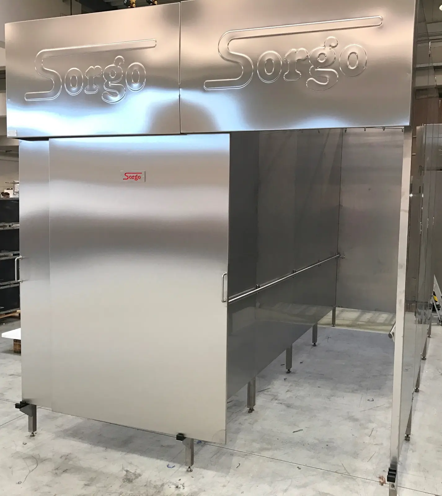
RAPID COOLING · PRODUCT SAFETY
SORGO blast chilling systems combine targeted cold air, water showering and mist with individually calculated stainless steel finned-tube coils. The increased surface area delivers high cooling capacity in a confined space; product load, trolley format and desired cooling time determine the project-specific design.
APPLICATION AREAS
PROCESS SEQUENCE
COOLING PROCESSES & OPTIONS
Every blast chilling system combines intensive recirculating-air cooling with a cooling shower integrated as standard. Optional systems extend cooling methods and cleaning.
Cooling takes place in parallel through powerful, targeted recirculating air and an integrated cooling shower. This removes heat from the product quickly and evenly.
Automatic cleaning adapted to system geometry is available as an option.
Critical temperature ranges are passed through quickly and in a controlled manner.
Rapid, controlled cooling protects product yield.
The desired core temperature is reached without intermediate storage.
Cold storage rooms and additional storage areas can be saved.
The system can optionally be equipped with a special stainless steel 1.4301 two-fluid atomising nozzle per loading trolley. Operating with compressed air and water, it sprays hot, hanging or horizontally placed products with microfine mist. The greatly increased water surface area improves evaporative cooling: heat is removed from the product while water consumption remains low.
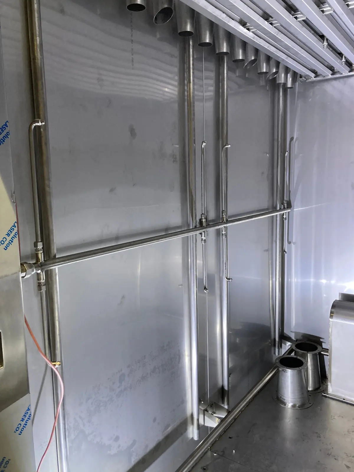
COOLING COILS · IN-HOUSE MANUFACTURE
SORGO manufactures cooling coils from stainless-steel finned tubes. Sizing and integration are matched to product load and cooling time. The image shows the intensive cooling system, not a steam coil.
Design, manufacturing and integration from one source – without unnecessary interfaces with external coil suppliers.
Tubes, fins, headers and distributors are manufactured in hygienic stainless steel and supplied with suitable control valves.
Project-specific designs for CO₂, Freon/HFC, glycol, ammonia and other agreed refrigerants.
Project-specific design and integration matched to the temperature range, capacity and available energy supply.
Intensive cooling systems have no steam coil. For optional cooking, process heat is supplied by electricity, gas or oil, depending on the configuration. The cooking function uses water injection and steam generation within the process.
Blast chilling
SORGO ENGINEERING · PRODUCT QUALITY
Powerful air movement supports short cooling times and protects product yield.
Air distribution is designed for comparable conditions at the top, bottom, centre, left and right of the trolley.
Each trolley position has its own fan motor with a stainless steel impeller manufactured in-house by SORGO.
Individual fans can be serviced selectively and replaced individually in multi-trolley systems.
If an individual fan fails, functioning trolley positions in a multi-trolley system remain usable.
One cleaning station can clean several connected systems sequentially in defined sequences. The CIP pipes are not insulated.
CONTROL & PROCESS DOCUMENTATION
Intuitive operation on a 15.6-inch industrial touchscreen, storable programmes and precise process control. Also discover SORGO INSPECT for central documentation and optional remote operation via smartphone or tablet.
Operation is adapted to the chilling, showering and other functions actually installed in the system.
Discover control & process documentation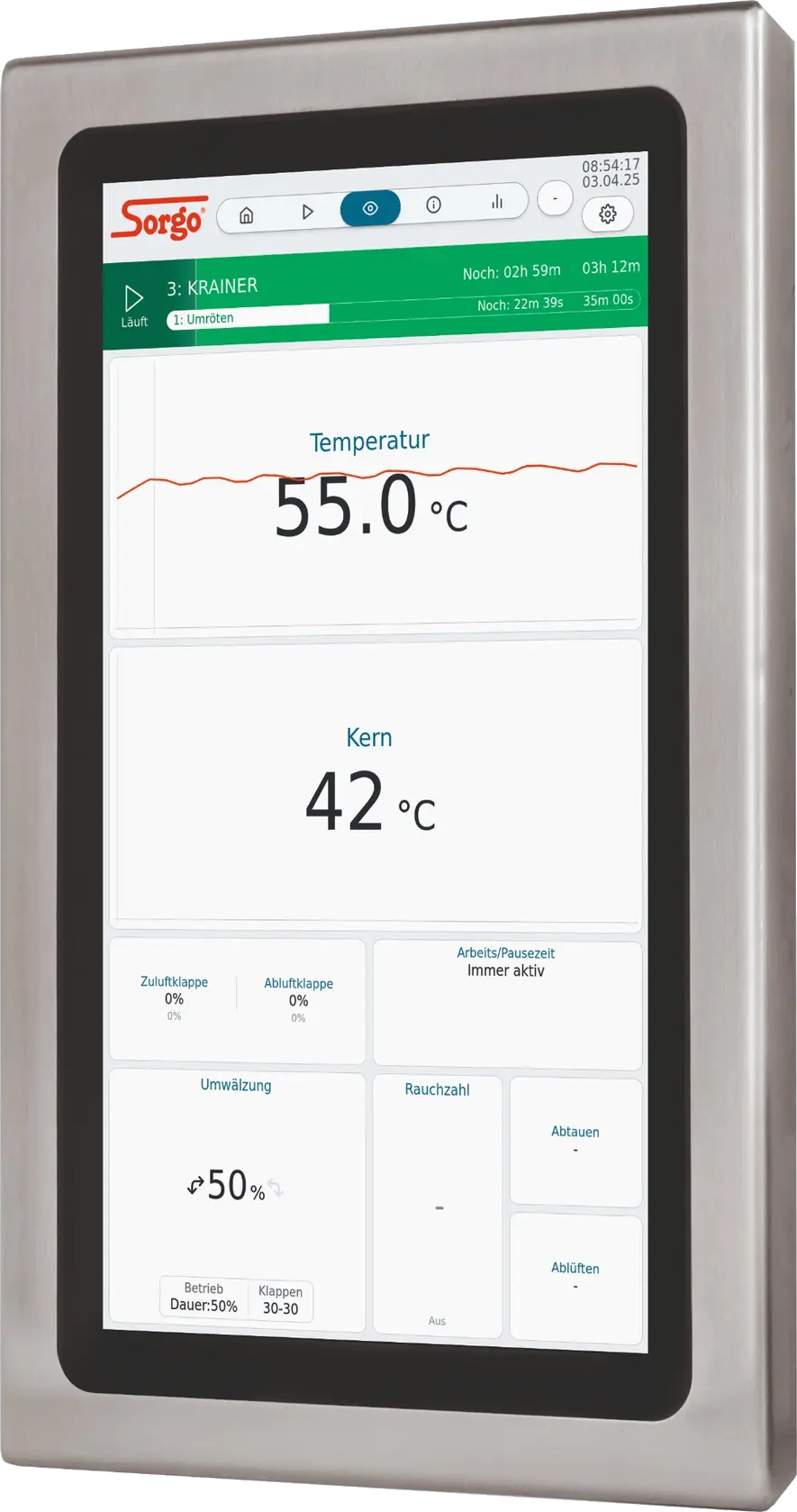
CONFIGURATION & DETAILS
TECHNISCHE AUSLEGUNG
Wählen Sie Kochfunktion, Reihenanordnung und Kältemedium. Die Tabelle zeigt die gesicherten IK-Baugrößen und berechnet 15 kW Kälteleistung je Beschickungswagen.
Die Auswahl dient als technische Planungsgrundlage für die Intensivkühlanlage.
Kälteleistung · 15 kW Kälteleistung je Beschickungswagen bei −15 °C Vorlauftemperatur.
Intensivkühlanlagen haben kein Dampfregister. Bei optionaler Koch-/Garfunktion wird die Prozesswärme je nach Ausführung elektrisch, mit Gas oder Öl bereitgestellt. Die Koch-/Garfunktion erfolgt über Wassereinspeisung und Dampferzeugung im Prozess.
| Typ | Wagen | Wagenmaß | Anlagenabmessungen | Kälteleistung | E-Anschlussleistung |
|---|---|---|---|---|---|
| IK 3.000 | 11-reihig | 1000 x 1000 x 2000 mm | B 1450 x T 1290 x H 2820 mmAnlagengehäuse+ 300 mm Umluftmotor | 15 kWKältemedium · GlykolVorlauf −15 °C | 4 kW |
| IK 6.000 | 21-reihig | 1000 x 1000 x 2000 mm | B 1450 x T 2350 x H 2820 mmAnlagengehäuse+ 300 mm Umluftmotor | 30 kWKältemedium · GlykolVorlauf −15 °C | 7 kW |
| IK 9.000 | 31-reihig | 1000 x 1000 x 2000 mm | B 1450 x T 3440 x H 2820 mmAnlagengehäuse+ 300 mm Umluftmotor | 45 kWKältemedium · GlykolVorlauf −15 °C | 10 kW |
| IK 12.000 | 41-reihig | 1000 x 1000 x 2000 mm | B 1450 x T 4520 x H 2820 mmAnlagengehäuse+ 300 mm Umluftmotor | 60 kWKältemedium · GlykolVorlauf −15 °C | 13 kW |
| IK 15.000 | 51-reihig | 1000 x 1000 x 2000 mm | B 1450 x T 5600 x H 2820 mmAnlagengehäuse+ 300 mm Umluftmotor | 75 kWKältemedium · GlykolVorlauf −15 °C | 16 kW |
| IK 18.000 | 61-reihig | 1000 x 1000 x 2000 mm | B 1450 x T 6680 x H 2820 mmAnlagengehäuse+ 300 mm Umluftmotor | 90 kWKältemedium · GlykolVorlauf −15 °C | 19 kW |
| IK 24.000 | 81-reihig | 1000 x 1000 x 2000 mm | B 1450 x T 8840 x H 2820 mmAnlagengehäuse+ 300 mm Umluftmotor | 120 kWKältemedium · GlykolVorlauf −15 °C | 25 kW |
| IK 30.000 | 101-reihig | 1000 x 1000 x 2000 mm | B 1450 x T 11000 x H 2820 mmAnlagengehäuse+ 300 mm Umluftmotor | 150 kWKältemedium · GlykolVorlauf −15 °C | 31 kW |
| IK 36.000 | 121-reihig | 1000 x 1000 x 2000 mm | B 1450 x T 13160 x H 2820 mmAnlagengehäuse+ 300 mm Umluftmotor | 180 kWKältemedium · GlykolVorlauf −15 °C | 37 kW |
Die Höhe wird getrennt für das Anlagengehäuse und die zusätzlichen 300 mm für den Umluftmotor angegeben. Die Kälteleistung gilt bei −15 °C Vorlauftemperatur. Alle Werte sind Richtwerte; jede SORGO Intensivkühlanlage wird individuell ausgelegt und gefertigt.
Die vollständige Tabelle mit Ihrer aktuellen Auswahl als PDF im A3-Querformat.
TAILORED TO YOUR NEEDS
Capacity, product, trolley format, energy supply, room layout and level of automation determine the solution. SORGO plans every system for the actual operating workflow – including controls, smoke system, cleaning, documentation, installation and commissioning.